Or search by topic
Number and algebra
Geometry and measure
Probability and statistics
Working mathematically
Advanced mathematics
For younger learners
Published 2011 Revised 2012
Electromagnetism
Electromagnetism describes the relationship between magnetism and electricity. The concept of the electric field was first introduced by Michael Faraday; the electric field not only describes the region surrounding an electrically charged body but in addition the force experienced by any further charges placed within this region. When electrical charges are in motion they induce magnetic
fields. Such phenomena are observed when iron shavings align in the presence of a magnetic field induced by the passage of a current through a nearby wire. A changing magnetic field will induce an electric field; similarly a changing electric field will induce a magnetic field. This is the concept of electromagnetic induction, it is the principle used to drive generators, motors, transformers,
amplifiers and many more electrical devices.
Electric Field Theory
Coulomb's Law
The electric force between two charged bodies is a non contact force. This forces acts along a line which connects the geometrical centres of the two charges. The force is proportional to the product of the charges and inversely proportional to the square of their separation. By Newton's third law it is seen that the force exerted by charge one on charge two is equal and opposite to that exerted
by charge two on charge one.
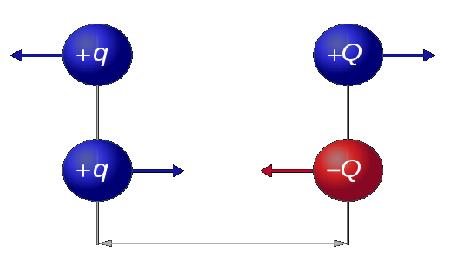
The force exerted by charge one on charge two is given in vector form below.
$\bf{F_{12}} = \frac{1}{4 \pi \epsilon_{0}} \frac{Q_1Q_2}{\bf{r^2}} \bf{r_{12}}$
where
$\epsilon_{0} \approx 8.854 \times 10^{-12} Fm^{-1}$ (electric constant)
$F$ - Force
$\bf r$ - separation between charge centres
$Q$ - Charge
$\bf{r_{12}}$ is a unit vector which points from the centre of charge one to the centre of charge two. The force is repulsive if the two charges are the same sign and attractive if the charges are of opposite sign. It should be noted that ordinary matter will acquire only a small amount of charge (measured in coulombs). The example below best illustrates this point.
Example:
Find the force between two point charges, each charged to +1 coulomb and separated by 1 metre.
$\bf{F_{12}} = \frac{1}{4 \pi \epsilon_{0}} \frac{Q_1Q_2}{\bf{r^2}} {\bf r_{12}} $ = $\frac{1}{4 \pi \epsilon_0} \approx 9 \times 10^9$ N
This is obviously an extremely large force; typically a charged body will carry charge of the order of a nano/micro coulomb.
Electric Potential
The potential difference between two points is the work done on (or by) a unit of positive charge when moving from one point to the other. When the charge passes through impedance (when the circuit is driven with direct current, there is no difference between impedance and resistance) it must do work but when passing through a battery has work done on it.
$v_b - v_a = \int_a^b \bf{E} d\bf {r}$
In order to define the electric potential at some point we must find the potential difference between this point and some other point at which the potential is zero (this condition is satisfied at an infinite distance from the point charge whose field we describe). The electric potential is therefore the work done against an electric field in moving a unit positive charge from infinity to some
distance r from the centre of the charge whose field it enters. Mathematically it is described as follows:
$\bf V = \int_{r}^{\infty} \bf{E} \bf{dl}$
The electric potential is typically measured in joules per coulomb or volts.
Electric Field Intensity, E
The electric field intensity $\bf{E}$ is defined as the force exerted on a positive test charge placed in a field. The field lines hence point in the direction that a positive charge would accelerate if placed in the field.
$\bf E = \frac{\bf F}{q}$
If we substitute $\bf {F}$ from Coulomb's law, we see that the electric field intensity due to charge $Q_1$ is:
$\bf{E} =\frac{1}{4 \pi \epsilon_{0}} \frac{Q_1}{r^2} \bf{r_{12}}$
The above shows us that $\bf{E}$ obeys an inverse square law: the field intensity decays as $\frac{1}{r^2}$. In fact, it is true that any point source which spreads its influence equally in all directions will obey such a law, this can be deduced from geometrical considerations alone, examples include gravitational fields, EM radiation and sound.
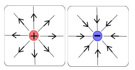
The common conventions adopted for drawing electric fields are described below.
Density of field lines:
The density of the field lines describes the magnitude of the field. A closer packing of field lines indicates a stronger field. Field lines commonly diverge as distance from the charged body increases -` this indicates a decaying field strength.
Orientation of field lines for conductors:
Field lines are always drawn perpendicular to the surface of the body whose field they describe; there is never a component of the electric field parallel to the surface of the body.
Intersection of field lines:
Electric field lines must never intersect. The electric field lines indicate the direction of the electromagnetic force in a given region of space. If field lines were to allowed to cross at some point in space then the direction of the force would be indeterminate at this point of intersection (we would effectively be defining two separate fields)
Electric Flux
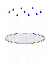
The electric flux is equal to the total amount of electric field passing through a virtual surface area perpendicular to the field.
Flux = $\phi = \int \bf{E} \cdot \bf {dA}$
Here, $\bf E$ is the electric field and $dA$ is a differential element of unit area on the closed surface with an outward facing normal defining its direction.
Superposition
The principle of superposition states that the response of any linear systems to several inputs is equal to the sum of the responses produced if each of the inputs was applied separately. Applying this idea to electrostatics we see that when several charges are present, the resulting electric field may be found by the vector summation of the electric field produced by each individual charge. It
should be noted that the principle of superposition is a very important concept occurring in many engineering applications.
Gauss's Law
Gauss's law states that the total amount of electric flux emerging from and normal to a surface is equal to the total electric charge enclosed. As a consequence, the electric charge enclosed within a surface is zero when the flux entering the surface is equal to the flux emerging. In integral form, Gauss's law is as follows:
$\int \bf{D} \cdot \bf{da} = Q$,
where
$\bf {D}$ is the dielectric field intensity, the dielectric field intensity takes the same value when passing from one dielectric to another.
$\bf{D} = \epsilon_0 \epsilon_r \bf{E}$ ($\epsilon_r $ is the relative permittivity of the material)
If we can find a surface which is always normal to the electric field we can simplify this calculation significantly by removal of the dot product.
For a point charge we should select a sphere as our Gaussian surface. $A =4 \pi r^2$
For a line of charge we should select a cylinder as our Gaussian surface. $A =2\pi r l$
For a plane of charge (such as a capacitor) we should simply select a plane as our Gaussian surface. Care should be taken to ensure both sides of the plane are considered.
Capacitance
We define capacitance as the charge stored per unit volt:
$C = \frac{dQ}{dV}$
A capacitor is simply a pair of conductors separated by a dielectric material, a device which provides short term storage of energy in the form of displaced charge. When a potential difference is applied across the conductors an electric field is produced in the dielectric, it is this electric field which provides a means of energy storage. At a sufficiently high voltage the molecular structure
of an insulator breaks down, electrons are torn out of their atoms and the material begins to conduct. The maximum voltage which we may apply to a material before it collapses and begins to conduct is known as the breakdown voltage. We must always operate a capacitor below this breakdown voltage. The choice of dielectric material will determine the application of a capacitor, typical applications
are listed below.
Air: Used in radio tuning devices.
Glass: Used in high voltage applications, NASA have been known to use glass dielectric capacitors to initialize space shuttle circuitry and help to deploy space probes.
Ceramic: Used in high frequency applications such as antennas and X-ray machines.
We know that the voltage is work done per unit charge, we may now use this idea to find the energy stored within an electric field.
$dw = V dQ$ = $\frac{Q}{C} dQ$
W = $\int \frac{Q}{C} dQ = \frac{Q^2}{2C} = \frac{Q}{2V} = \frac{CV^2}{2}$
The simplest form of a capacitor is the parallel plate capacitor, shown below:
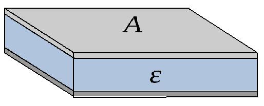
Each plate is charged to an equal and opposite charge, if the plates are of infinite size a uniform electric field will exist between them. It is the even distribution of charge caused by mutual repulsion of like charges (on a plate) that leads to the generation of the uniform field. In practice, a plate area much greater than plate separation gives minimal field divergence at the plate ends
(fringing effects), we can therefore treat the field as uniform.
Question:
Using the concepts of Gauss's Law, superposition, electric potential and capacitance, prove that the E field between between the plates of a parallel plate capacitor is uniform and find the capacitance. The plate separation is d and the relative permittivity of the dielectric $\epsilon_r$, in addition it can be assumed A is much greater than d.
Solution:
Step 1: Gauss's Law defines the electric field produced by a single plate.
$\int \bf{D} \cdot \bf{da}$ = $ \epsilon_0\epsilon_r \bf{E} A = Q $
$\bf{E} = \frac{Q}{A \epsilon_0\epsilon_r }$
Step 2: Principle of superposition
We have two plates; each plate is storing charge and hence produces an electric field. At a distance x from the upper plate both the upper and lower plate are each producing a field of
$\bf{E} = \frac{Q}{A \epsilon_0\epsilon_r }$
Only half of this field enters the dielectric between the conductors, the other half emerges from the opposite side of the plate and does not contribute. The total electric field is therefore found by superposition.
$\bf E = \frac{1}{2} \frac{Q}{A \epsilon_0\epsilon_r} + \frac{1}{2} \frac{Q}{A \epsilon_0 \epsilon_r }= \frac{Q}{A \epsilon_0\epsilon_r }$
This function of $\bf E$ is independent of position between plates (x), the field is therefore uniform.
Step 3: Electric Potential
$\bf{V} = \int_0^d \bf {E(r)} dr$ =$\int_0^d \frac{Q}{A \epsilon_0\epsilon_r } dr$ = $ \frac{Qd}{A \epsilon_0\epsilon_r }$
Step 4: Capacitance
$C=\frac{dq}{dv}$
If th e charge is not changing with time.
$C = \frac{Q}{V}$
$C = \frac{Q}{V}$ = $\frac{ A \epsilon_0\epsilon_r }{d}$
This shows us that the capacitance is proportional to the area of the plates and inversely proportional to their separation.
Capacitor Charge and Discharge
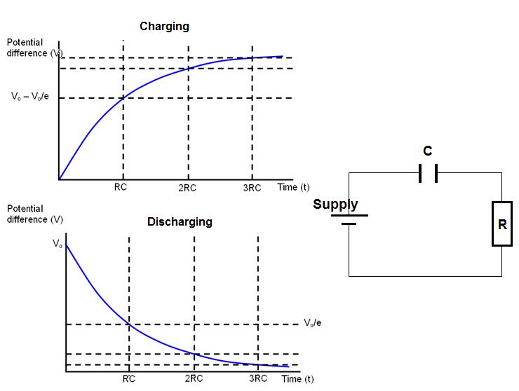
It is the potential difference between the supply and capacitor that causes charge to flow from one plate to the other. The system wishes to be in a state of equilibrium. Charge will therefore flow until the potential difference across the capacitor matches that of the supply (until there is no potential difference between supply and capacitor). Electrons are taken from one plate and transferred
to the other; one becomes positive and the other progressively more negative. As charge builds up on the capacitor the voltage across it increases, the potential difference between the battery and the capacitor decreases and hence the rate of charging decays. This could be analysed using Kirchhoff's voltage law; we know that the sum of the emfs is equal to the sum of the voltage drops.
$V_{supply} = V_c + V_R = V_c + IR$
$I =\frac{V_{supply} - V_c}{R}$
We see that the current (rate of flow of charge) and hence the rate of charging/discharging is proportional to the potential difference between supply and capacitor. The voltage of the supply is constant but the voltage of the capacitor varies with charge according to $C = \frac{Q}{V}$
Charge: $V = V_0 e^{\frac{-t}{RC}}$
Discharge: $V = V_0 ( 1 - e^{\frac{-t}{RC}})$
Question:
Use Ohm's law, Kirchhoff's voltage law and the definition of capacitance to derive the equation of a charging capacitor for a simple circuit consisting of a cell, resistor and capacitor.
Solution: $I = \frac{dQ}{dt}$
$V_{supply} = V_c + IR = \frac{Q}{C} + R\frac{dQ}{dt}$
This is a first order differential equation in Q.
$\frac{dQ}{dt} + \frac{Q}{RC} = \frac{V}{R} $
The integrating factor is $e^{\frac{t}{RC}}$
$Q e^{\frac{t}{RC}} = \int \frac{V_{supply}}{R} e^{\frac{t}{RC}} dt = V_{supply}Ce^{ \frac{t}{RC}} + D$, where D is a constant
$Q =V_{supply}C + D e^{\frac{-t}{RC}} $
At $t = 0$, $Q = 0$, therefore $D = -V_{supply}C$ and $Q = V_{supply}C(1 - e^{\frac{-t}{RC}} )$
Using the definition of capacitance ($V =\frac{Q}{C}$)
$V = V_{supply}C(1 - e^{\frac{-t}{RC}} )$
Capacitors in Series:
For capacitors placed in series we know that each will store the same amount of charge but may have a different voltage across it.
$V_{total} = V_1 + V_2 +... +V_n$
$C=\frac{Q}{V}$
$\frac{Q}{C_{total}} = \frac{Q}{C_1} + \frac{Q}{C_2} +... +\frac{Q}{C_n} $
$\frac{1}{C_{total}} = \frac{1}{C_1} + \frac{1}{C_2} +...+ \frac{1}{C_n} $
Capacitors in parallel:
For capacitors placed in parallel we know that each has the same voltage across it but may have a different charge stored.
$Q_{total} = Q_1 + Q_2 +... +Q_n$
$C_{total}V = C_1 V + C_2 V +... +C_n V$
$C_{total} = C_1 + C_2 +...+ C_n $
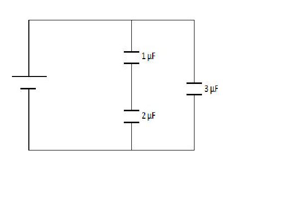
Question: Find the capacitance of the circuit below.
Solution:
The 1 µF capacitor and the 2 µF capacitor combine in series:
$\frac{1}{C_{series}} =\frac{1}{2 µF} + \frac{1}{1 µF} $
$C_{series} = 6.67 \times 10^{-7} F$
We can now combine this capacitance in parallel with the 3 µF capacitor to find that:
$C_{total} = .67 \times 10^{-7} + 3 \times 10^{-6} = 3.67 \times 10^{-6} = 3.67 µF$
Magnetic Field Theory
Magnetic fields are the result of electric charges in motion; this can be currents flowing through wires or simply electrons in their atomic orbits.
Magnetic Field Intensity
The magnetic flux density (or field intensity), $\bf{B}$, is defined by the Lorentz force. The Lorentz force describes the force experienced by a charge $Q$ moving at a velocity $\bf {v}$ in superposed electric and magnetic fields.
$\bf{F} = q( \bf{E} +\bf{V} \times \bf{B})$
In the absence of the electric field the above becomes
$\bf{F} = q\bf V \times \bf{B}$,
where:
$q$ - Magnitude of charge
$V$ - velocity vector of charge
$B$ - magnetic flux density
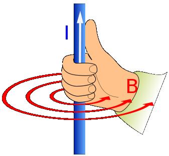
The above equation describes the vector nature of the B field, attention should be paid to the cross product in the above equation, it indicates that the B-field is always perpendicular to both the flow of charge and the magnetic force. The direction of the magnetic flux density can be found from the right hand thumb rule. When your right hand thumb points in the direction of the current (in the
direction of the velocity vector) then your fingers will curl in the direction of $\bf{B}$.
By noting that I = $\frac{dq}{dt}$ we can derive the force experienced by a current carrying wire placed within a magnetic field. If we substitute $q=It$ into the Lorenz force law we find that:
$\bf{F} = q\bf{V} \times \bf{B} = It\bf{V}\times\bf{B}$
But the velocity of the charge multiplied by the magnitude of the charge is simply the length of the wire passed in a unit of time ($L$).
$\bf F = L \bf I \times \bf B = BIL \sin \theta$
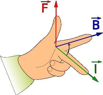
If we know the direction of any one of the force, field or current then the other two may be deduced by Fleming's left hand rule. Extend the thumb, forefinger, and the middle finger of your left hand such that all the three are mutually perpendicular to each other, if the thumb points in direction of the force then the forefinger points in the direction of the B field and the middle finger in the
direction of the current. This is illustrated below.
Magnetic Flux
The concept of magnetic flux is very convenient for the description of Faraday's law (which will be discussed shortly). The magnetic flux is the total amount of magnetic field passing through a virtual surface area perpendicular to the field.
Flux $\phi = \int \bf{B} \cdot \bf{dA}$
Where $B$ is the magnetic flux density and $dA$ is a differential area on the closed surface with an outward facing surface normal defining its direction.
The flux linkage is equal to the product of the flux and the number of turns of the object that is being linked.
$\phi ' = \phi N$
Ampere's Law
Ampere's law describes the relationship between magnetic fields and currents in a similar way to how Gauss's law describes the relationship between electric fields and charge. Ampere's law states that for any closed loop, the line integral of field intensity ($H =\frac{B}{\mu_0\mu_r}$ ) is equal to the current linked.
$\int \bf{H} dl = N I$
Amperes law allows us to find an expression for the B field as a function of current. Below is an example to illustrate this.
Question:
Using Ampere's law find an expression for the magnetic field intensity around a current carrying wire.
Solution:
We must first identify the path which the B-field will take. Using the right hand rule we know that the B-field will encircle the current, the differential path which the current will take is therefore dl = $2\pi dr$ (where r is the distance from the wire).
$\int \bf{H} dl = \int \bf{H} 2\pi dr = I$ (N=1 as we are considering only one wire)
$\frac{ B 2\pi r }{\mu_0\mu_r } = I$
$B = \frac{\mu_0\mu_r I}{2\pi r}$
Faraday's Law of Induction
Faraday's law of electromagnetic induction is an extremely important principle, it is fundamental to the generation of most of the electrical power in the modern world. Faraday's law describes how a change in magnetic flux threading a circuit induces a voltage seeking to oppose this change in flux. The induced voltage is proportional to the rate of change of flux linkage.
$V =- N \frac{d\phi}{dt}$
The minus sign simply indicates that the direction of the induced current is such that its magnetic field opposes the change in flux (Lenz's Law). There are typically two methods for inducing a voltage, flux cutting and flux linking.
Flux cutting: When lines of flux are cut by conductors. E.g. Dropping a magnet through a coil of wire.
Flux Linking: Varying the direction or magnitude of the B-field.
Question:
A plane of wingspan 42m flies through a vertical field of strength 5 x $10^{-4}$T. Calculate the emf induced across the wing tips if its velocity = 130 ms$^{-1}$.
Solution:
$V = -N \frac{d\phi}{dt} = \frac{\Delta {BA}}{\Delta {t}} = B L V = 5 \times 10^{-4}\times 42\times 130 = 2.73 V $
Inductors
Inductors are passive electrical components. They store energy in the form of moving charge (or a magnetic field). Typically inductors take the form of a coil of wire (similar to a solenoid). The reason for looping the coil is to increase the flux linkage and hence increase potential for energy storage. Electric current passing through the inductor induces a magnetic field around it, a time
varying current will produce a time varying magnetic field and in accordance with Faraday a voltage. The inductance is therefore the voltage induced per unit charge, its units are Henrys (H).
$V = L \frac{dI}{dt} = Lq$
The symbol of an ideal inductor is shown:

Inductors in Series:
For inductors placed in series we know that the current through each will be the same but may have a different voltage across it.
$V_{total} = V_1 + V_2 +... +V_n$
$L=\frac{V}{Q}$
$\frac{L_{total}}{Q} = \frac{L_1}{Q} + \frac{L_2}{Q} +... +\frac{L_3}{Q} $
$L_{total} = L_1 + L_2 +... +L_n$
Inductors in parallel:
For inductors placed in parallel we know that each has the same voltage across it but may have a different current through it.
$Q_{total} = Q_1 + Q_2 +... +Q_n$
$\frac{V}{L_{total}}= \frac{V}{L_1} + \frac{V}{L_2} +... +\frac{V}{L_n} $
$\frac{1}{L_{total}}= \frac{1}{L_1} + \frac{1}{L_2} +... +\frac{1}{L_n} $
Applications of Electromagnetic Induction
Many electrical devices operate on the principle of electromagnetic induction. These include motors, generators, transformers, microphones and speakers (some of which are described below).
AC Generator
AC generators operate on the principle of electromagnetic induction; they are devices which convert mechanical energy into electrical energy. The turning of a coil within a magnetic field induces a potential difference across the coil and hence a current through it. The induced emf forces charge (already present within the wire) to flow through an external circuit and hence produces electricity.
The initial mechanical energy can be produced by a range of devices, such as water falling through a turbine, wind turbines or steam turbines.
AC Motor
A current carrying wire within a magnetic field will experience a force; this is the basic principle of a motor. A current is passed through a coil, this produces a B-field around the coil, this B-field then interacts with the permanent B field in which the coil sits, vector superposition of the fields leads to cancelation in some regions and addition in others, the net effect is a resultant
force and hence a turning moment about the coil. This torque forces the wire to rotate; mechanical energy has thus been converted into electrical.
Transformer
A transformer is a device which is used to transform electrical power from one voltage and current level to another. In its most simple form a transformer is comprised of a primary winding, a secondary winding and an iron core. the iron core transmits the flux from one winding to the other, this is illustrated below.
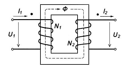
Transformers operate in accordance with Faradays law of electromagnetic induction. By passing an alternating current through the primary winding we induce a time varying B-field, this B-field is then transmitted via the iron core to the secondary winding. Varying this B-field over the secondary winding will induce an alternating voltage across it and hence an alternating current through it. If
the transformer is ideal the voltage induced is described by the formula below.
$\frac{V_1}{V_2} = \frac{N_1}{N_2}$
We see that two types of transformer are therefore possible, one which steps a voltage up and one which steps a voltage down. If the number of turns of the secondary winding is greater than that of the primary the voltage will be stepped up. If the number of turns of the primary is greater than that of the secondary the voltage will be stepped down.
In order for a real transformer to be modelled as ideal it must satisfy the conditions listed below:
The internal resistance of the windings must be negligibly small.
The reluctance of the iron must be negligibly small (we must assume iron is a perfect conductor of flux).
All the flux linking the primary must link the secondary; no flux leakage occurs as the flux bends around the corners.
No real or reactive power is consumed.
Real transformers are typically able to achieve very high efficiencies, often as high as 99%. Transformer losses are divided into two subcategories; copper losses (losses associated with the windings) and iron losses (losses associated with the core).
Copper losses are a consequence of resistive heating, these losses are also referred to as $I^2 R$ losses and are very much dependent on the magnitude of the current. At high frequencies additional losses occur due to a phenomenon known as the skin effect, electrical current is effectively only allowed to flow through the outer skin of the conductor. We know from faraday and Lenz that the induced
voltage is proportional to the rate of change of flux, furthermore it acts in a direction opposing the change which caused it. A high frequency current will therefore induce a large current which will oppose itself. We know that the B-field induced by a current carrying wire decays with distance from the wire centre, the B-field and hence the opposing current is therefore largest at the centre of
a winding, this strong opposing current results in current cancelation throughout the centre of the wire, current hence only flows in the skin.
Iron losses are most commonly associated with hysteresis and eddy currents. Each time the magnetic field reverses it must do some work against atomic dipoles it previously aligned, this is known as hysteresis loss. Eddy currents circulate throughout the core in a plane which is perpendicular to the flux, these therefore result in resistive heating.
Typical transformer applications are described below:
Power Transmission:
When power is transmitted it is desirable to step the voltage up and hence step the current down, this is done to minimise the $I^2 R$ losses associated with joule heating. When the power is then received by the consumer, the voltage must be stepped down again before domestic use.
Measurement of High Voltages and Currents:
Transformers are often used to step down a high voltage or current to a safe level before measurement.
Continuous Variation Of Voltage and Current Levels:
Machinery often requires power at a continuously varying voltage and current level.
You may also like
Lunar Leaper
Gravity on the Moon is about 1/6th that on the Earth. A pole-vaulter 2 metres tall can clear a 5 metres pole on the Earth. How high a pole could he clear on the Moon?
Whoosh
A ball whooshes down a slide and hits another ball which flies off the slide horizontally as a projectile. How far does it go?

